


Send Message
Privacy statement: Your privacy is very important to Us. Our company promises not to disclose your personal information to any external company with out your explicit permission.

HU NAN YUBANG MAGNETIC MATERIAL CO.,LTD
 May 09, 2023
Brushless DC motor operating principle diagram, the winding is a three-phase star connection method, 120 degree uniform, three-phase half-bridge drive mode, the rotor is a pair of poles. In the illustrated position, the pole center line of the magnetic steel is aligned with the A-phase winding. At this time, the control circuit makes the S1 switch tube turn on and off according to the rotor position detection signal, and the B-phase winding is energized, under the action of the magnetic field of the B-phase winding. The rotor will rotate 120 clockwise clockwise to reach the position shown by the dashed rotor. The magnetic pole centerline aligns with the B phase winding. At this time, the control circuit turns off the S1 switch tube according to the rotor position detection signal, making the S3 switch tube. Turn on, the A-phase winding is energized. Under the action of the magnetic field of the A-phase winding, the rotor will rotate 120 degrees clockwise, and will be turned on in the above power-on sequence, and the rotor will rotate clockwise. Brushless DC motor acquisition of rotor position signal, the former, the motor structure is simple, but the motor is difficult to start; the latter, the motor structure is slightly more complicated, but the start is stable and reliable, most of the current brushless DC motor uses the latter. There are many types of position sensors, and brushless DC motors for air conditioning generally use Hall elements as position sensors.
The stator winding of the motor is often made into a three-phase symmetrical star connection, which is very similar to a three-phase asynchronous motor. The rotor of the motor is affixed with magnetized permanent magnets. In order to detect the polarity of the motor rotor, a position sensor is installed in the motor. The driver consists of power electronics and integrated circuits. Its functions are: receiving the start, stop, and brake signals of the motor to control the start, stop, and brake of the motor; receiving the position sensor signal and the forward/reverse signal to control the inverse Change the on and off of each power tube of the bridge to generate continuous torque; accept the speed command and speed feedback signal to control and adjust the speed; provide protection and display, etc. Since the brushless DC motor is operated autonomously, it does not add starter windings on the rotor like a synchronous motor with heavy-duty start under heavy-duty speed regulation, nor does it cause oscillation and out-of-step when the load suddenly changes.
The Hall signal is passed to the controller. The controller powers the motor coil through the motor phase wire (thick line, not the Hall wire), the motor rotates, the magnet and the coil (to be exact, the coil wound on the stator, in fact, Hall Normally installed on the stator.) When rotation occurs, Hall signals a new position signal. The thick wire of the controller changes the current direction of the motor coil again. The motor continues to rotate (when the position of the coil and the magnet changes, the coil must correspond. Change the direction of the current so that the motor can continue to move in one direction, otherwise the motor will oscillate from one position to the next, rather than continuously.) This is electronic commutation.
as the picture shows
Brushless motor internal structure circuit
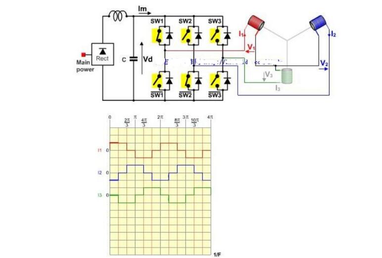
Brushless DC motor drive principleThe stator of a brushless DC motor is a coil winding armature, and the rotor is a Permanent Magnet. If only a fixed DC current is applied to the motor, the motor can only produce a constant magnetic field, the motor cannot rotate, only the position of the rotor of the motor is detected in real time, and the corresponding current is applied to the different phases of the motor according to the position of the rotor. The stator generates a rotating magnetic field with a uniform direction, and the motor can rotate with the magnetic field.
Figure 1.4 shows the schematic diagram of the principle of rotation of the brushless DC motor. For convenience of description, the center of the coil of the stator of the motor is connected to the power supply of the motor, the terminals of each phase are connected to the power tube, and the position of the position sensor is turned on to make the G electrode of the power transistor connected. 12V, the power tube is turned on, and the corresponding phase coil is energized. Because the three position sensors turn on with the rotation of the rotor, the corresponding phase coils are also energized sequentially, so that the direction of the magnetic field generated by the stator also changes, and the rotor of the motor also rotates. This is the reason for brushless DC motors. The basic principle of rotation is to detect the position of the rotor and energize each phase in turn so that the direction of the magnetic field generated by the stator changes continuously and uniformly.

The permanent magnet brushless DC motor developed on the basis of the traditional DC motor is basically the same in structure. The difference is that the armature winding of the permanent magnet brushless DC motor is placed on the stator, similar to the winding of the AC motor. At the same time, generally adopt the form of multiphase, among which the three-phase application is the most in the current situation; the rotor is a permanent magnet and adopts electronic commutation, and the interaction between the stator magnetic field and the permanent magnetic field of the rotor generates electromagnetic torque. Permanent magnet brushless DC motor according to the shape of the permanent magnet and magnetic circuit structure, the air gap magnetic field waveforms are three kinds of square wave, trapezoidal wave, sine wave, the waveform of the back EMF corresponding to the same. In general, a back-EMF motor is a sine-wave motor called a permanent-magnet synchronous motor, as shown in Fig. 3; waveforms of other two types are called a permanent-magnet brushless DC motor, as shown in Fig. 4.

The composition of the permanent magnet brushless DC motor is shown in Figure 5. From this we can see that it consists of three main parts. The structure of the rotor is salient pole type and embedded type, and is made of permanent magnetic material. The armature on the stator is the opposite of a permanent magnet brushed DC motor, so it has a rotating magnetic field and a fixed armature.

The power tube in the electronic switching circuit can be directly connected with the armature winding of the motor, and the position sensor is added, and its function is equivalent to the mechanical commutation device in the brush motor. The permanent magnet brushless DC motor has a simple structure, and its basic structure diagram is shown in FIG. 6 .

Permanent magnet brushless DC motor structure shown in Figure 7. As can be seen from the figure, after the DC power of the switching circuit is supplied to the stator windings, the control system controls the position of the position sensor to realize the control of the switching circuit, correctly determines the energization and power-off status of each motor winding, and then realizes the motor. The reversal.

Brushless direct motor drive method can be divided into a variety of drive methods according to different categories, they have their own characteristics.
Press the drive waveform:
(1) This type of driving is easy to implement and it is easy to realize motor position sensorless control;
(2) This kind of driving method can improve the motor operation effect and make the output torque uniform, but the implementation process is relatively complicated. At the same time, this method has two methods: SPWM and SVPWM (Space Vector PWM). SVPWM is better than SPWM.
Why no brushless motor ferriteFrequently asked by users why brushless motors do not use ferrite magnets? Why not use ferrite? What is the reason?
In a brushless motor, there is no carbon brush, and contrary to the brush, the magnet of the brushless motor becomes a rotor. Brushless motors, especially brushless motors in the model sector, and almost 100% NdFeB magnets, mainly due to the strong magnetic properties of NdFeB, the power of the motor is closely related to the performance of the magnet, and the volume and grade of the Neodymium Magnet determine the The maximum power of the motor.
Everyone knows that ferrite has low performance and low performance leads to low motor power, so it is rarely used. Brushless motors usually use sintered NdFeB (magnetic tile) materials, bonded NdFeB (ring) material, brushless motor with magnetic tile as the stator, generally more than 6 poles, but the magnetic tile as a brushless The rotor of the motor can have 4 or more poles.
The diameter of the magnetic ring of the brushless motor is generally greater than 20, and the number of magnetic poles is between 4-12 poles, and the wall thickness thereof is mostly between 1.5-5.0.
Cooler Water Pump Magnet,Ferrite Pump Magnets,Anisotropic Ferrite Magnets,Isotropic Ferrite Magnets
The above is the Why brushless motor does not use ferrite we have listed for you. You can submit the following form to obtain more industry information we provide for you.
You can visit our website or contact us, and we will provide the latest consultation and solutions
Send Inquiry
Most Popular
lastest New
Related Products
Send Inquiry
Privacy statement: Your privacy is very important to Us. Our company promises not to disclose your personal information to any external company with out your explicit permission.
Fill in more information so that we can get in touch with you faster
Privacy statement: Your privacy is very important to Us. Our company promises not to disclose your personal information to any external company with out your explicit permission.